Table of Contents
Purpose
This post explains the advantages of Intermittent Fault Detection simultaneously and continuously monitoring of every test point (deterministic testing) of a Unit Under Test (UUT) in comparison to digital single circuit scanning, sampling capability (parametric testing) as found in conventional test equipment currently deployed across the sustainment enterprise.
Scanning / Sampling Test Methodology
Conventional circuit testers switch between test points and take a single or multiple readings / measurements before switching to the next test point. Therefore, for a component or wiring harness with ‘n’ test points, ‘n-1’ test points are not undergoing any testing at any given moment. During the switching process itself ‘n’ test points are not being tested at all. Therefore, test coverage is extremely limited and all intermittent and transient faults are likely to be missed due to conventional testing process of scanning through each line one at a time – there is a negligible chance of detecting intermittent faults that cause No Fault Found (NFF) test results.
This is illustrated in the graphic below with the red areas representing the ‘switching & acquisition’ periods and the green areas representing the ‘testing’ periods. The graphic shows a representation of the test coverage over a 360milli-second period from a scanning methodology perspective. Scanning ‘Tester A’ applies a 5:1 ratio of switching: testing and ‘Tester B’ applies a 1:2.6 ratio of switching: testing.
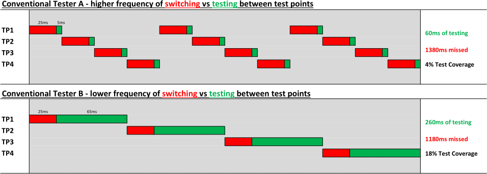
From the graphic above it can be seen that even if switching and acquisition time were improved significantly, the test coverage is still severely limited; for Tester A the missed testing (cumulative figure across all the 4 test points) is 1380milli-seconds (i.e. 4 x 360ms minus 60ms). Even if the red sections were reduced to virtually zero and the test period for each test point maximized, the best possible test coverage would be only 25% for four test points. As the test points increases by n, the test coverage reduces proportionally i.e. 1/n x 100%.
Therefore, for a wire harness or LRU chassis with 500 test points the maximum test coverage available is only 0.2% of a defined test period. Even the highest performing scanning technologies can only switch through 150-200 test points per second, so for the wire harness or LRU with 500 test points 499 test points are not being tested at any one time; and during switching all 500 test points are not being tested.
Scanning systems like the AWTS are literally taking a snapshot of the state of the wire or circuit and comparing it with other samples of the same wire that have been previously hard coded into the Test Program Set (TPS). Anything that happens between each of the samples is unseen, and it is unlikely that one sample will provide enough information to allow the tester to identify that the state of the wire is actually changing. As the number of test points increases, the time between the samples must also increase, reducing the possibility of detecting a given duration intermittent event increasing the likelihood of NFF test results. Moreover, to ensure detection of a given fault period is guaranteed, the frequency of scanning must increase by the Number of Test Points divided by the Required Detectable Fault Duration.
Number of Test Points / Required Detectable Fault Duration
To detect a 1millisecond fault duration for 500 test points the tester must scan at 0.5MHz.
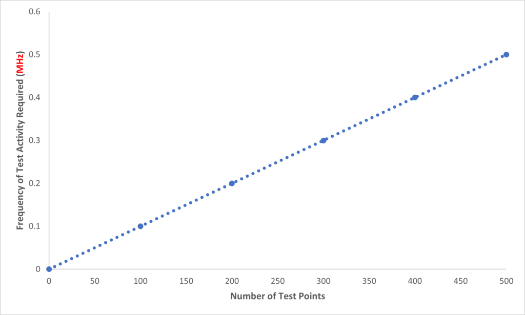
This sampling rate has an inverse effect on the time needed to perform the necessary testing activity; in this case the available time to perform a test activity is 2 micro-seconds.
A short sampling time for a commercial instrument is about 20 micro-seconds, although it is recognized that with custom hardware design this could be reduced; although this would have an adverse effect on accuracy. However, while the switching activity could be reduced, the wire or circuit would still need about 20 to 30 micro-seconds to charge and stabilize before a measurement activity could be carried out; this activity is the primary limiting factor of scanning techniques and a significant contributor to No Fault Found (NFF) and Cannot Duplicate (CND) activity. With this limitation, it will take a minimum of 15 milliseconds to switch circuits, charge, stabilize and measure 500 test points even with a custom design. A commercial instrument would slow down the sample time to approximately 50micro-seconds (30micro-seconds to settle and 20micro-seconds to sample) resulting in a time of 25milli-seconds to sample 500 test points. Therefore, the ‘Required Detectable Fault Duration’ could only be 25 milli-seconds. High grade Digital Multi Meters (DMM) and tester manufactures claim that the fastest sampling is in the milli-second region which would mean that the ‘Required Detectable Fault Duration’ would increase by a factor of 1000 to approximately 25 seconds for 500 test points and would only credibly enter the milli-second domain at approximately 20 test points.
While the theory suggests that a ‘Required Detectable Fault Duration’ of 25 milli-seconds period can be detected on 500 test points, the practicalities are far more challenging. With fast switching times and short duration of charging time, these activities introduce noise into the system, so a further testing activity is required to filter out unwanted noise from the reading; this becomes the second limiting factor to scanning. This is because up until now, it has been considered that the intermittent fault is a perfect square wave of a defined period. However, the intermittent fault is a minor, almost random, change in the ohmic characteristics of the test point and it yields a jagged profile with a variance in both amplitude and duration (see Department of Defense MIL-HDBK 527 “Guidance for IFE”).
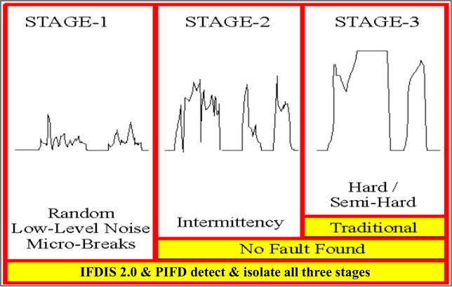
This means that any filtering algorithms are likely to filter out the detected fault and so most faults will be ignored and go undetected. Moreover, because the faults are not cyclic, it will be impossible to average out the effects of the filtering to allow the intermittent fault to become dominant among the noise.
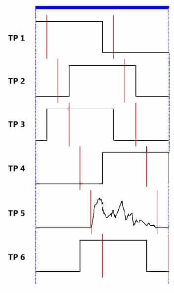
The graphic to the left shows the scanning of 6 test points over a 1 second period (shown by the blue bar).
Five of the test points are showing a perfect square wave as an intermittent fault. From the diagram it can be seen that the scanning frequency for the test activities shown in red is 12Hz for 6 test points to be able to detect a 0.5 second intermittent fault. Therefore, it is likely that the faults on five of the TPs will be detected.
However, intermittency is more representative by the trace on the TP 5, therefore, it is unlikely that scanning technology would detect this type of fault unless it was perfectly synchronous with the scanning measurement window.
If the test activity is successful in detecting the fault as shown on TP 2, and the test activity is in the last part of the fault’s duration, it is then impossible to perform any other testing activities, for example isolation of the fault and characterizations of the fault.
In summary, scanning technology is capable of detecting long duration (wide open circuit) faults, but as the number of test points increases, so the scanning frequency has to increase to ensure confidence in detection. However, this brings new challenges such as a limited time for test activity and of course all of the time while a test is being performed on one of the test points, no testing is being performed on the other test points; therefore, test coverage is extremely limited.
Portable Intermittent Fault Detector™ (PIFD™) – Simultaneous & Continuous Monitoring
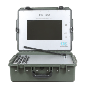 Intermittent Fault Detection (IFD) technology, that includes the Intermittent Fault Detection & Isolation System™ (IFDIS™), Intermittent Fault Detection & Isolation System 2.0™ (IFDIS 2.0™), and the Portable Intermittent Fault Detector™ (PIFD™), have a hardware analog neural-network that allows for simultaneous and continuous monitoring of hundreds or even thousands of test points. This provides for increased probability of detection due to the differences outlined above. IFD technology does not scan or sample. It monitors all circuits in parallel with super sensitivity (momentary discontinuities as short as 50 nanoseconds) as if having a latching oscilloscope monitoring every test point of the Unit Under Test (UUT). This technology is the only proven tester to meet MIL-PRF-32516 and has authority to operate on the Joint Strike Fighter F-35 weapon system as well as all Boeing commercial aircraft platforms.
The IFDIS, IFDIS 2.0, and PIFD have been objectively proven to enhance sustained readiness recovery, increase operational readiness, reduce maintenance costs, and significantly improve electronic functionality.
Universal Synaptics family of Intermittent Fault Detection technology offerings that have utilized Artificial Intelligence, neural networks, and machine learning since 1996, are encouraged that AI, neural networks, and machine learning have now been recognized in 2022 as a “hot emerging trend” for DoD sustainment activities.
Conventional Testers A and B listed above in this article provide 4% and 18% test coverage, respectively. This will be true for all Automatic Test Equipment (ATE) or other conventional testers that follow the same methodologies and processes for testing across the U.S. DoD or other conventional wire testers, including the AWTS. In fact, the DoD owns and operates over $50B worth of conventional test systems, yet the intermittent failure problem that manifests as NFF test results has ballooned to $5B annually. IFD technology, monitoring all circuits simultaneously and continuously, provides 100% test coverage as highlighted in the graphic below representing the PIFD in comparison to Conventional Testers A and B and similar test equipment.

Summary
The demonstrated advantages in detection probability are why IFD technology is actively reducing the intermittent / NFF problem down to a five minute test in a typical avionics system as outlined. These rather simple to compute metrics also show conclusively why IFD technology works so well for resolving the intermittent / NFF problem. IFD technology sees real intermittent circuit occurrences that conventional test equipment cannot see and was not designed to see or detect. Given this giant leap forward in test coverage, it becomes crystal clear why the IFD is the only objectively proven MIL-PRF-32516 compliant technology designed specifically for, and capable of, detecting, resolving, and gauging the overall problem and levels of intermittent / NFF anomalies that occur in an operational environment.
Related Articles:
