U.S. Department of Defense Intermittent Fault Definition
“A discontinuity that occurs in LRU/WRA chassis and backplane conductive paths as a result of various operational environmental stimuli, including, but not limited to, thermal stress, vibrational stress, gravitational G-force loading, moisture and/or contaminant exposure; as well as changes in the material due to age and use, such as tin whiskers, metal migration and delamination of materials. These faults can occur individually and/or in rapid succession on any chassis or backplane circuit.” (Source: US DoD MIL-PRF-32516)
Intermittent Faults / No Fault Found (NFF)
The Testing Problem
- Intermittence occurs randomly in time, place, amplitude, and duration, and is responsible for:
- $5.5 billion in annual loss to the DoD (Source: 2022 OSD Memo Addressing Electronics Intermittence Across DoD’s Sustainment Enterprise)
- 383,000 days of non-availability of end-item sub-components to the DoD (Source: 2022 OSD Memo Addressing Electronics Intermittence Across DoD’s Sustainment Enterprise)
- The nature of the intermittence failure mode suggests that the ability to detect and further isolate faults to root cause is based on two things:
- Test detection SENSITIVITY
- Test detection PROBABILITY
- Conventional approaches likes those listed below are parametric (low probability) methods concentrating on ohmic measurement accuracy and/or system functionality
- Intermittent events cannot be detected until they occur and there are limited opportunities to capture these events on the specific circuit when it does manifest
- To detect and isolate intermittent issues on the ground requires phenomenal testing speed (SENSITIVTY) and 100% bandwidth / test point or circuit coverage (PROBABILITY)
- Proper technology intermittent fault detection must be able to test all of the failing system’s lines all of the time in a simultaneous and continuous fashion
- Conventional test equipment, similar to those listed above, fail with one or the other, SENSIVITY or PROBABILITY
- The U.S. Dept. of Defense maintains 400+ types of test systems and spent $50+ billion to buy and support these systems over a 12-year period, according to the GAO (Military Readiness: DOD Needs to Better Manage Automatic Test Equipment Modernization GAO-03-451)
- None of the test systems deployed within the DoD are solving the intermittent / NFF problem
The Testing Solution
- To address all of the testing limitations above and to have the ability to detect and isolate faults to root cause, a tester must solve:
- Test detection SENSITIVITY
- Test detection PROBABILITY
- Intermittent Fault Detection (IFD) Technology was purpose-built to fulfill these requirements and solve the intermittent fault / NFF failure mode
- IFD leverages patented super-sensitive analog neural network detection technology on the front end and digital reporting and data processing technology on the back end, while testing efficiently with parallel, simultaneous circuitry monitoring
- IFD consistently detects any intermittent event on any circuit, simultaneously, at ohmic glitch durations as short as 50 nanoseconds
- Number of simultaneous test point monitoring and detection is scalable from 128 to over 30,000 test points, depending on UUT requirements
Intermittent Fault Detection Technology Objectively Proven to Solve NFF
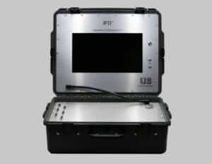
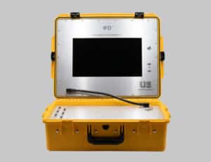
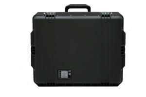
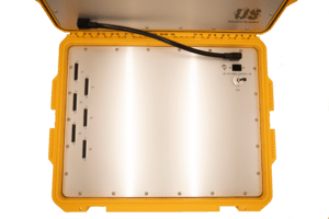
Portable Intermittent Fault Detector™ (PIFD™)
- MIL-PRF-32516 Compliant
- Portable, lightweight design
- Fast and accurate intermittent fault detection in EWIS, harnesses, and small components
- Detect intermittent faults, open circuits, shorted circuits, and mis-wiring
- AutoMap™ technology eliminates need for Test Program Set (TPS) software development
- 128, 256, and 512 test point variants
- F-35 Authority-to-Operate (ATO)
- Technology Readiness Level (TRL) 9
- Boeing AMM Insertion for all type/model/series of aircraft
- National Stock Number (NSN) listed:
- PIFD-256 6625-01-696-1902
- PIFD-512 6625-01-696-1235
- Available in Integrated Logistics Support-Specific (ILS-S)
- MIL-STD 202G Compliant
- MIL-STD 461 Compliant
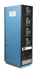
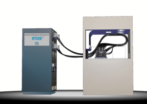
Intermittent Fault Detection and Isolation System 2.0™ (IFDIS 2.0™)
- MIL-PRF-32516 Compliant
- Utilized in depots and back shops
- Fast and accurate intermittent fault detection in avionics
- Detect intermittent faults, open circuits, shorted circuits, and mis-wiring
- AutoMap™ technology eliminates need for Test Program Set (TPS) software development
- Easily expandable in 1,280 test point increments
- Single of Dual Rack option based on test requirement
- Technology Readiness Level (TRL) 9
- Simulated environment for LRUs with all-lines-all-of-the-time circuit monitoring

Conventional Technologies
Conventional Automatic Test Equipment (ATE) is not designed or optimized to detect momentary intermittent failures that cause NFF. The scientific discovery that conventional ATEs inability to detect and isolate intermittent faults in electrical and avionics component interconnections and wiring has been conclusively linked to the $5.5 billion dollar problem.
Functional ATE and Continuity Testers Cannot Detect and Isolate Intermittent Faults
- Tests only one function at a time
- Tests only one circuit at a time, even when connected to multiple circuits
- Digital averaging, scanning, and sampling masks / misses the intermittent faults
- “testing blind spot” or “testing void” exists
- Line Replaceable Units (LRUs) / Weapon Replaceable Assemblies (WRAs) / Electrical Wiring Interconnect Systems (EWIS) / cable harnesses / cable sets are rarely tested in an operational environment
- Failures occur under operational profiles
- Testing is conducted in static environment
- Only designed to find functional failures, failed components, and hard failures
- Open circuit continuity issues
- High resistance issues
- Short circuits
- Functional ATE and Continuity Testers that serially scan or are manual one line at a time testers, include:
- Fluke DMMs
- Eclypse AWTS to include 4-wire Kelvin
- Astronics WIFT
- DIT-MCO
Digital Multi-Meters (DMMs)
- Record sample ohmic resistance readings and, over a specific period, averages them out before presenting them to the user display
- Digital Averaging occurs with DMMs as most will sample at a high rate of 17 milliseconds
- Automatically averages out a high ohmic sample event that appears insignificant over a thousand readings
- Renders DMMs incapable of detecting Category 3 or shorter (501 microseconds to 5 milliseconds) ohmic intermittent faults, as per MIL-PRF-32516
- Most conventional wiring Continuity testers incorporate DMMs as their underlying testing technology
- Only testing one line or circuit at a time
- Any intermittent event(s) randomly manifesting on other lines or circuits not actively being tested are missed (NFF)
- Single Circuit Tester
Hi-Pot Testers
- Rely on the breakdown of the insulation to show if there is a fault
- Technique stresses the Unit Under Test (UUT) and can actually damage the insulation on sites that would otherwise have not caused a problem
- Some recognized military forces have banned high voltage insulation testing following the NTSB report into the cause of the loss of TWA Flight 800 in 1996
- Hi-Pot testing can actually mask low-level microbreak intermittent faults and can result in a false negative result
- Single Circuit Tester
Low Energy High Voltage
- Does not reliably detect intermittent faults, but less destructive than Hi-Pot, because they use a low energy pulse
- Depending on the type of intermittent fault(s), higher voltages to expose the fault(s) may be needed to expose the fault possibly resulting in same negatives with Hi-Pot
- On commencement of testing it is difficult to determine what voltage level to use
- Method assumes that intermittent faults have an adjacent cable with exposed conducting material which is not always the case, resulting in low detection probabilities that are scenario driven
- Single Circuit Tester
Time Domain Reflectometry (TDR)
- Advanced technology that can detect cable changes using complex signals, reading reflections, and carrying out post analysis
- Detection rate is limited to approximately 50 millisecond changes – intermittent faults below this threshold cannot be detected
- Applied to only one wire per cable loom and switching approach between wires eliminates the probability of finding intermittent events
- Single Circuit Tester
4-Wire Kelvin (currently being marketed as Certified Test Protocol (CTP))
- Invented in 1861, 4-wire Kelvin is an archaic test that has not moved the readiness needle
- High resolution measurements are taken to determine finite changes in resistance
- Measures fractions of a milli-ohm on a single wire or circuit
- Requires 4 wires per wire/circuit under test (2 inputs, 2 outputs) i.e. for a 100 wire harness, 400 interface wires are required to conduct testing
- All continuity testers can perform 4-wire Kelvin testing
Oscilloscopes
- Can be set up to have a latching trigger and defined trigger parameters to detect and latch a particular condition
- Generally do not have a self-stimulus and so this needs to be provided as a 3rd party aspect of the test when using an oscilloscope in this mode
- Setting up triggers and releasing the latching trigger in time for capturing subsequent fault(s) is an extremely complex technique and it would only be applicable for a single line at a time
- Applicable for laboratory environments
- Time consuming if it were to be applied to all suspected intermittent lines during fault investigations and would require 100s to 1000s of o-scopes
- Single Circuit Tester
Related Articles:
